

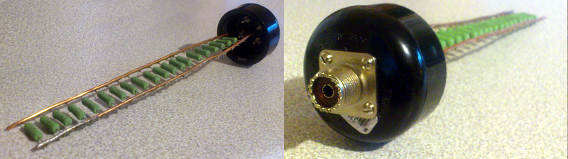
Calling something a “dummy” is usually not a compliment. In the world of electronics, though, a dummy load is the quiet genius in the corner. It does not complain, demand a software update, or vanish halfway through a test because someone forgot to charge it. It simply accepts power, behaves predictably, and tells you whether your equipment is ready for the real world.
A dummy load is one of the most useful tools for testing power supplies, batteries, chargers, radio transmitters, solar equipment, and other electrical systems. It imitates the demand that a real device would place on a circuit without requiring the actual device to be connected. That may sound boring, but boring is wonderful when the alternative is discovering a design flaw after a product reaches customers.
Whether you are troubleshooting a radio, validating a USB charger, testing a battery pack, or checking a new power supply, a dummy load helps you ask a simple but important question: What happens when this thing finally has to do some work?
What Is a Dummy Load?
A dummy load is a test device that absorbs electrical energy in a controlled way. In many cases, it converts that energy into heat. Instead of connecting a power source to a motor, a computer board, a radio antenna, or a battery-powered gadget, you connect it to a dummy load that simulates the expected operating conditions.
Think of it as a stand-in actor for your electrical system. The dummy load walks onto the stage, takes the stress, and reveals whether the star of the show is prepared. If the power supply maintains voltage, the radio transmitter stays stable, and the battery behaves properly, the test is a success. If smoke appears, the dummy load has performed an unintended but highly educational dramatic role.
In direct-current testing, a dummy load often takes the form of a resistor bank or an electronic load. In radio-frequency testing, it is commonly a carefully designed termination that matches the transmitter’s expected impedance, often 50 ohms. The goal is to absorb the transmitted power without sending unwanted radio signals into the air.
Why a Real Device Is Not Always the Best Test Tool
Testing with the real product may seem logical. After all, a phone charger should be tested with a phone, and a transmitter should be tested with an antenna. The problem is that real devices are inconsistent. A phone may change its charging behavior. A motor may pull a different current as temperature rises. An antenna may introduce reflections, interference, weather-related changes, and enough mystery to make a detective request overtime.
A dummy load gives engineers and technicians repeatability. You can set a specific current, resistance, or power level and run the same test again and again. That makes it easier to compare results, identify defects, and determine whether a change improved the design or merely made the graph look more exciting.
Repeatable testing matters because products rarely fail under perfect conditions. A power supply may look excellent while sitting nearly idle, then sag when demand increases. A battery pack may appear healthy until it is asked to deliver current continuously. A radio transmitter may work on paper but become unhappy when connected to a poorly matched load. Dummy loads make those weak points easier to find before the real world does it for you.
DC Dummy Loads: Testing Power Supplies, Batteries, and Chargers
For DC electronics, a dummy load is often called an electronic load. Unlike a simple resistor, an electronic load can be programmed to draw a controlled amount of current or power. It acts as a power sink, pulling energy from a power supply, battery, fuel cell, solar panel, or charger while measuring how the source responds.
Constant Current Mode
In constant current mode, the electronic load draws a fixed amount of current. This is useful for checking whether a power source can deliver a promised output. For example, a charger rated for 5 volts and 3 amps should be evaluated under a realistic load rather than given a polite handshake and declared successful.
If the load is set to draw 1 amp, 2 amps, and then 3 amps, the tester can monitor whether voltage remains within specification. A small change may be acceptable. A dramatic voltage collapse is a clue that the power source is not ready for prime time.
Constant Resistance Mode
In constant resistance mode, the dummy load behaves like a resistor with a fixed value. This can help simulate devices that naturally look resistive to the power source. It is useful when testing circuits where voltage and current change together according to the relationship between resistance, voltage, and current.
This mode may sound plain, but plain is useful. Many technical problems appear only when a source sees a predictable resistive load. A design that handles one operating point beautifully may stumble at another, especially when wiring resistance, heat, or voltage drop becomes part of the story.
Constant Power Mode
In constant power mode, the load draws enough current to maintain a chosen power level. Since electrical power is calculated as voltage multiplied by current, the load adjusts current as voltage changes. This can imitate certain real-world devices that attempt to maintain their power consumption even when supply voltage shifts.
This is where testing becomes especially revealing. As voltage falls, a constant-power load may demand more current. That can expose weak cables, undersized connectors, poor regulation, or battery limitations. It is less a polite examination and more a job interview with follow-up questions.
Transient Mode
Transient testing changes the load quickly between two or more levels. This is valuable because modern electronics do not always draw power smoothly. Processors, motors, wireless radios, LED systems, and digital devices can change their current demand very quickly.
A power supply must respond without producing too much voltage dip, overshoot, ringing, or instability. A dummy load that creates controlled current steps can show whether capacitors, regulators, control loops, and wiring are doing their jobs. In other words, it reveals whether the system remains calm when life gets hectic.
RF Dummy Loads: Letting Radios Talk Without Broadcasting
In radio-frequency work, a dummy load has a different but equally important purpose. A radio transmitter expects to see a specific impedance at its output, often 50 ohms. A proper RF dummy load provides that match while converting the transmitter’s output power into heat instead of radiating it through an antenna.
This allows technicians and radio operators to tune, measure, troubleshoot, and validate transmitters without unintentionally sending signals into the surrounding environment. It also helps protect equipment. A poor impedance match can cause power to reflect back toward the transmitter, creating stress that the equipment may not appreciate.
RF dummy loads are rated for power and frequency range. A load suitable for a low-power radio may not be suitable for a high-power amplifier. Likewise, a load that behaves well at one frequency range may not be accurate at much higher frequencies. The lesson is simple: “It has a connector that fits” is not a complete engineering specification.
What a Dummy Load Can Teach You
1. Specifications Are Promises, Not Proof
A label that says “12 volts, 10 amps” is a starting point, not a victory parade. A dummy load allows you to test whether the source can maintain that output under increasing demand. It moves the conversation from marketing language to measurable behavior.
Good testing checks more than whether the unit turns on. It looks at voltage regulation, current capability, thermal behavior, noise, protection features, and recovery after a load change. A device that performs well for ten seconds may behave very differently after thirty minutes. Heat has a way of editing overly optimistic assumptions.
2. Heat Is Information
Dummy loads convert energy into heat, which means temperature is part of the test result. Excessive heat can indicate that a load is being pushed beyond its rating, cooling is inadequate, or the test duration is unrealistic. The dummy load may be doing exactly what it was designed to do, but physics still insists on collecting payment.
When testing higher-power equipment, thermal management matters. Airflow, duty cycle, heatsinks, cooling systems, and temperature limits should all be considered. A load that can handle a certain power level briefly may not be designed for continuous operation at that level.
3. Stable Results Require Stable Test Conditions
A poor cable, loose connection, undersized wire, or weak connector can make a good product appear faulty. That is why reliable testing requires attention to the full setup, not merely the device under test. Electrical measurements are only as trustworthy as the path between the source, the load, and the measuring instruments.
For low-voltage, high-current testing, small voltage drops in leads can become significant. For RF testing, connector quality, cable condition, impedance matching, and frequency capability all influence the result. The dummy load teaches a valuable lesson: test equipment is part of the experiment, not background decoration.
4. Realistic Stress Reveals Useful Truths
A device that runs perfectly at no load has completed the easiest exam imaginable. The important question is what happens when demand rises, changes quickly, or continues for a long period. Dummy loads allow controlled stress testing without risking a more expensive piece of equipment.
For a battery, that may mean discharging at different current levels. For a solar panel, it may mean checking output under changing load conditions. For a power supply, it may mean stepping between light and heavy demand. For a transmitter, it may mean confirming output power and stability into a proper matched termination.
5. Good Testing Makes Failures Cheaper
The cost of a dummy load is usually much lower than the cost of replacing damaged equipment, investigating field failures, or explaining to a customer why a product only works when nobody uses it. A controlled load turns surprises into data. That is one of the best bargains in engineering.
How to Choose the Right Dummy Load
Selecting a dummy load starts with understanding the system you are testing. For DC applications, consider voltage range, maximum current, maximum power, operating modes, measurement accuracy, cooling, and whether you need automated test sequences or data logging.
For example, a hobby project may need a modest load for testing small DC adapters or battery packs. A production environment may need programmable electronic loads that can repeat test profiles, capture measurements, and communicate with software. The right tool depends on whether you are checking one device on a bench or evaluating hundreds of units every day.
For RF applications, look at impedance, frequency range, connector type, power rating, duty cycle, and cooling requirements. A 50-ohm load is common, but it must also be suitable for the expected frequency and power. A small termination can be perfect for a signal generator and completely unsuitable for a transmitter that thinks “warm” is merely a suggestion.
Safe Dummy Load Testing Practices
Dummy loads are test tools, not invincibility charms. Always respect the voltage, current, power, temperature, and time ratings of the load. Start with conservative settings, confirm connections, and keep the work area clear. High-power loads can become very hot, and high-current circuits can produce serious hazards when wiring or protection is inadequate.
Use appropriately rated leads and connectors, avoid touching equipment that may be hot, and do not assume a load is safe simply because it looks inactive. In many cases, the quietest piece of equipment on the bench is the one converting a remarkable amount of energy into heat.
Experience-Inspired Field Notes: Lessons From the Bench
The most memorable dummy-load lessons usually begin with confidence. Someone has a new power supply, a fresh set of leads, and a device that worked perfectly during a quick test. Everything appears ready. Then the dummy load is connected, current is increased, and the voltage begins to wander like it has suddenly remembered an appointment elsewhere.
One common experience involves inexpensive power adapters. At light load, many of them look respectable. The meter reads close to the advertised voltage, the indicator light glows proudly, and everyone is tempted to declare the project complete. Add a heavier load, though, and the voltage may sag, ripple may increase, or the adapter may become far warmer than expected. The dummy load did not create the problem. It simply stopped the adapter from hiding it.
Another familiar scenario involves batteries. A battery may show a healthy voltage when nothing is connected, leading people to assume it is fully capable. But voltage without load is only part of the story. Once the battery is asked to supply current, internal resistance and remaining capacity become more obvious. A controlled load test can show whether the voltage holds, falls gradually, or drops so quickly that the battery is essentially offering a dramatic farewell speech.
Technicians also learn that cables deserve more respect than they usually receive. A power source may pass its test when measured directly at its terminals but fail when connected through thin, damaged, or overly long leads. The dummy load helps uncover this because it demands enough current to make voltage drop visible. Suddenly, the “mysterious power supply problem” turns out to be a cable with the electrical personality of a garden hose full of marshmallows.
In RF work, the experience can be equally humbling. A transmitter may seem to function normally with an antenna connected, but the antenna system adds variables: location, weather, feedline condition, nearby objects, and reflections. Connecting a suitable dummy load gives the transmitter a known, controlled termination. When output power and stability improve with the dummy load, the test points toward the antenna system, cable, connectors, or matching network rather than the transmitter itself.
Dummy loads also teach patience. A quick test is useful, but a longer test often tells a more complete story. Components warm up. Cooling systems reach equilibrium. Protection circuits react. A power supply that looks strong for one minute may reduce output after ten minutes. An RF load that handles a brief transmission may become dangerously hot during continuous use. The time factor is not a nuisance; it is part of reality.
Perhaps the best practical lesson is that measurements should be written down. When you test at several current levels, record voltage, current, power, temperature, and duration. When testing a transmitter, record output power, frequency, load rating, and observed behavior. Notes turn a one-time experiment into useful knowledge. Without notes, every future test becomes a reunion with the phrase, “I’m pretty sure it worked last time.”
Finally, dummy-load testing encourages humility. Engineers, hobbyists, technicians, and product designers all make assumptions. The cable should be fine. The charger should deliver the rated current. The battery should be healthy. The radio should be stable. A dummy load does not care about confidence, experience, or persuasive hand gestures. It reports what the circuit actually does. That honesty is why a dummy load can teach so much.
Conclusion
A dummy load may not look exciting, but it is one of the most practical teachers in electronics and RF testing. It helps verify power supply performance, evaluate batteries, test chargers, analyze load response, troubleshoot transmitters, and reduce the risk of expensive surprises.
The lesson is bigger than the equipment itself: reliable systems are built by testing realistic conditions, measuring results, and respecting the difference between what a product claims and what it can actually deliver. A dummy load may be silent, but it has plenty to say.