

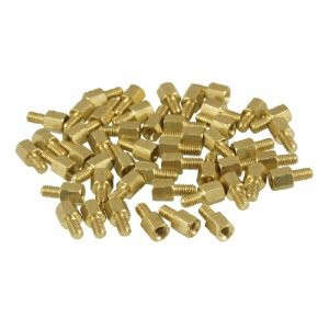
Some electronic components attract attention with glowing displays, humming fans, and specifications long enough to qualify as bedtime reading. The Amico Brass Screw PCB Standoffs Hexagonal Spacers M3 are not among them. These little gold-tone pillars quietly sit underneath a circuit board, doing the mechanical equivalent of holding a table steady while everyone else takes credit for dinner.
Small as they are, PCB standoffs perform several important jobs. They create clearance beneath a printed circuit board, prevent solder joints from contacting a chassis, provide consistent mounting points, and help keep the board from flexing when connectors, buttons, or cables are used. Brass versions can also provide an electrically conductive path when the mounting system is intentionally designed for chassis grounding.
The Amico M3 brass standoffs are especially relevant to compact DIY electronics, control boxes, prototype boards, computer accessories, embedded systems, and layered circuit assemblies. However, choosing them successfully requires more than matching the attractive gold color to your screwdriver collection. Thread size, body height, board clearance, mounting-hole location, electrical isolation, and tightening force all matter.
What Are Amico M3 Brass PCB Standoffs?
A standoff is a threaded mechanical separator used to hold one component at a fixed distance from another. In electronics, it commonly raises a printed circuit board above a metal plate, plastic enclosure, secondary circuit board, or equipment chassis.
The Amico product is a male-to-female hexagonal standoff. One end has an external male thread, while the opposite end contains a female threaded hole. The male end can screw into a threaded enclosure, nut, mounting plate, or another compatible standoff. An M3 screw can then be inserted through the PCB mounting hole and tightened into the female end.
According to the commonly published specifications for this Amico set, each standoff has approximately:
- An M3 threaded connection
- A 5 mm hexagonal body length
- A 5 mm male threaded stud
- An overall approximate length of 10 mm
- A maximum body width of about 5 mm
- A brass construction with a gold-tone appearance
- A package quantity of 50 standoffs
Those dimensions make the product a particularly compact mounting option. The important functional height is normally the length of the hexagonal body, not the combined body-and-stud measurement. In other words, a 5 mm body generally creates about 5 mm of space between the mounting surfaces once the male thread has been installed.
Understanding the M3 Thread Size
The “M3” designation refers to a metric thread with a nominal outside diameter of 3 mm. Standard coarse M3 hardware typically uses a 0.5 mm thread pitch, meaning the distance from one thread crest to the next is half a millimeter.
This does not mean every screw that looks approximately correct will fit. An imperial screw may begin to enter the thread and then bind, damage the brass, or become permanently committed to its new career as modern sculpture. Use properly specified M3 screws and verify the pitch when combining hardware from different kits or manufacturers.
Male-to-Female Configuration
The male-to-female design is useful because it reduces the number of loose nuts needed during assembly. The male stud anchors the standoff to the base, while the female side receives the PCB mounting screw. It also makes stacking possible when additional vertical space is needed, provided the threads engage correctly and the resulting assembly remains mechanically stable.
Why the Hexagonal Shape Matters
A round standoff can be difficult to grip once it begins rotating with the screw. The hexagonal body provides flat surfaces for a small wrench, nut driver, or suitable pliers. This allows one side to be held steady while the screw is tightened or removed.
The tool should fit the hex body closely. Oversized pliers can slip, chew the corners, or decorate the brass with marks that were not included in the original design brief.
Why Brass Is Used for PCB Standoffs
Brass is popular for electronic mounting hardware because it combines mechanical strength, machinability, conductivity, and reasonable resistance to corrosion in ordinary indoor environments. Fine threads can be cut accurately into brass, helping small screws engage smoothly when the parts are manufactured correctly.
Mechanical Stability
Brass standoffs are more rigid than typical nylon alternatives. That rigidity can be valuable when a board includes frequently used USB ports, terminal blocks, toggle switches, buttons, or cable connectors. Pressing or plugging into those components transfers force into the PCB, and well-positioned metal standoffs help resist movement.
They are still small threaded components, however. They should not be treated as structural supports for heavy transformers, large battery packs, motors, or other high-load equipment unless the complete assembly has been mechanically evaluated.
Electrical Conductivity
Unlike nylon, brass conducts electricity. This can be useful when a PCB mounting hole is intentionally connected to ground and the standoff is designed to bond that point to a conductive chassis.
Conductivity can also create problems. A brass standoff touching an exposed signal trace, solder pad, component lead, or unintended ground area may cause a short circuit. Metal mounting hardware should therefore be used only where the PCB layout provides adequate clearance around each mounting hole.
Corrosion Considerations
Brass generally performs well in normal indoor electronic assemblies, but it is not immune to environmental damage. Condensation, salt, aggressive chemicals, and prolonged outdoor exposure can cause corrosion or tarnishing. Mixed-metal assemblies may also experience galvanic effects in wet environments.
For outdoor controls, marine equipment, humid industrial spaces, or chemically exposed enclosures, the complete material combination should be reviewed rather than assuming that anything gold-colored is automatically invincible.
What Are These Hexagonal Spacers Used For?
The Amico M3 brass PCB standoffs can be useful in many low-load electronic and mechanical projects, including:
- Arduino-compatible controller enclosures
- Raspberry Pi accessory plates when the mounting pattern supports M3 hardware
- Custom sensor and relay boards
- Small power-supply modules
- LED lighting controllers
- Audio amplifier projects
- Robotics control compartments
- 3D-printed electronics enclosures
- Prototype test fixtures
- Stacked PCB assemblies
- Control panels and instrument boxes
- Lightweight acrylic display mounts
Compatibility should never be assumed from the word “PCB” alone. Many circuit boards use M2, M2.5, M3, 4-40, or other mounting systems. Some holes are intended only for plastic clips, while others lack enough surrounding clearance for a conductive metal support.
How to Determine Whether a 5 mm Standoff Is Tall Enough
Standoff height controls the distance between the underside of the PCB and the mounting surface. A 5 mm body is compact, which is excellent for a slim enclosure but less suitable for a board with tall solder joints or components mounted underneath.
Before installation, inspect the bottom of the board and identify the lowest projecting feature. This might be a connector pin, through-hole component lead, solder blob, heat sink clip, battery terminal, or pin-header tail. Measure its projection below the board and add a safety margin.
For example, if the longest soldered lead extends 2.5 mm below the PCB, a 5 mm standoff leaves approximately 2.5 mm of theoretical space. That may be sufficient in a stationary prototype, but additional room may be desirable if the enclosure can flex, the board may vibrate, or an insulating sheet will be installed beneath it.
Airflow and Heat
Clearance also affects ventilation. Raising a board allows air to move beneath it and prevents heat-producing components from sitting directly against the enclosure. A 5 mm gap offers some separation, but a hotter power board may benefit from taller standoffs or purpose-designed cooling.
Standoffs should not be treated as heat sinks unless the entire thermal path has been engineered for that purpose. They may conduct a small amount of heat through mounting areas, but they are primarily mechanical parts.
How to Install Amico M3 Brass Standoffs
1. Confirm the Mounting Pattern
Place the PCB above the enclosure or mounting plate and confirm that every hole aligns. Never force a board into position by tightening one corner and using the other screws as tiny mechanical negotiators. Misalignment introduces stress and may crack the board or damage solder joints.
2. Inspect the Mounting Holes
Check for copper pads, exposed traces, nearby leads, and underside components. Determine whether the holes are plated and whether they are connected to circuit ground. If electrical isolation is required, use insulating washers, shoulder washers, or nylon standoffs instead of allowing brass to contact the board directly.
3. Secure the Male Thread
Install each male stud into the threaded base, insert, nut, or compatible mounting point. Engage the thread by hand first. It should turn smoothly for several rotations. Immediate resistance may indicate cross-threading, dirt, damage, or the wrong thread standard.
4. Position the Circuit Board
Lower the PCB onto the standoffs without scraping components across the brass. All mounting holes should sit naturally above the female threads. If one corner must be pushed into alignment, stop and correct the mounting locations.
5. Insert the M3 Screws
Start every screw loosely before fully tightening any of them. This allows minor alignment adjustments and helps prevent the board from being twisted. Tighten gradually in an alternating pattern.
6. Use Modest Tightening Force
PCB laminate is not a suspension bridge, and the screw does not need to be tightened as though it is holding one together. Excessive torque can strip the internal brass thread, crush the board surface, damage plated mounting holes, or bow the PCB.
Tighten until the board is secure and no longer moves under gentle pressure. Use washers where appropriate to spread the clamping force.
Common Installation Mistakes
Using the Wrong Screw Length
A screw that is too short may engage only one or two threads. A screw that is too long may bottom out inside the standoff before it clamps the PCB. Measure the board thickness, washer thickness, available thread depth, and required engagement before selecting the screw.
Allowing Metal to Touch Live Circuit Areas
The brass body must not overlap exposed copper unless that contact is intentional. Check both sides of the board, particularly around mounting holes near power inputs, voltage regulators, and high-current traces.
Installing Too Few Supports
Four corner standoffs may be sufficient for a small, rigid board. A longer PCB or one with a heavily used center connector may need an additional support near the point where force is applied. Otherwise, the board can flex every time a cable is connected.
Stacking Without Checking Stability
Male-to-female standoffs can sometimes be joined to increase height, but every added connection creates another location that may loosen or lean. Taller assemblies are more sensitive to vibration and side loading. Use a purpose-made longer standoff when possible.
Mixing Metric and Imperial Hardware
M3 hardware can resemble certain imperial fasteners at a glance. Similar appearance does not mean compatible threads. Forcing one into the other can damage both pieces and transform a simple enclosure project into a lesson about patience.
Brass Versus Nylon, Aluminum, and Stainless Steel
Brass is not automatically the best choice for every PCB. The correct material depends on electrical, mechanical, environmental, and weight requirements.
Brass Standoffs
Brass offers good rigidity, clean threads, electrical conductivity, and a compact professional appearance. It is a strong option for grounded chassis assemblies and reusable prototypes, provided unintended electrical contact is prevented.
Nylon Standoffs
Nylon is lightweight and electrically insulating. It is often the safer choice when mounting-hole clearance is limited or the PCB must remain isolated from the enclosure. However, nylon threads are easier to strip, and the material may flex or creep under sustained load and heat.
Aluminum Standoffs
Aluminum hardware is lightweight and conductive. It is useful where reduced weight matters, but thread durability and galvanic compatibility should be considered.
Stainless Steel Standoffs
Stainless steel provides excellent strength and can perform well in demanding environments. It is generally harder than brass, which may be useful mechanically but less forgiving if threads become misaligned.
Buying and Quality-Control Checklist
Before purchasing or installing an Amico M3 brass standoff set, confirm the following:
- The circuit-board holes accommodate M3 screws.
- The base accepts an M3 male thread.
- A 5 mm body provides adequate underside clearance.
- The screw length matches the available female thread depth.
- Conductive brass is electrically appropriate for the design.
- The hex width fits the available space around nearby components.
- The package includes only the hardware expected for the project.
- The threads are clean, centered, and free from burrs.
Bulk hardware should be inspected before assembly. Try an M3 screw in several randomly selected pieces. Threads should engage smoothly, and the male studs should appear straight. Set aside any part with damaged threads, visible cracks, severe burrs, or an off-center hole.
Practical Experiences With Amico M3 Brass PCB Standoffs
The First Fit Usually Reveals Everything
In a typical enclosure build, the most informative moment comes before the screwdriver appears. Placing the bare PCB over the proposed mounting points quickly reveals whether the hole pattern, component clearance, and 5 mm height make sense. Builders who skip this dry fit often discover too late that a soldered header touches the enclosure or that one mounting post sits directly beneath a component lead.
A useful practice is to install the standoffs in the base, rest the unpowered board on top, and inspect the assembly from every side with a flashlight. The board should sit flat without rocking. No solder joint should contact the mounting surface, and each screw hole should align without sideways pressure.
Compact Height Is Both the Advantage and the Limitation
The 5 mm hex body works nicely in slim project boxes. It keeps the assembly tidy and avoids wasting vertical space. For a small sensor controller or low-profile relay board, the result can look much cleaner than an improvised stack of washers and nuts.
That same compact size can become inconvenient when long through-hole leads remain beneath the PCB. A freshly assembled prototype may have several pins extending farther than expected. Trimming those leads and checking for sharp solder peaks is often necessary before final mounting.
The lesson is straightforward: select standoff height from the underside of the board, not from the empty enclosure. The case may offer plenty of room, while one innocent-looking pin header quietly consumes most of the clearance.
The Hex Body Makes Maintenance Easier
During repeated assembly and disassembly, a standoff may begin turning with the top screw. The hexagonal body is particularly helpful here. A correctly sized wrench can hold the spacer while the screw is loosened, preventing the male stud from backing out of the enclosure.
Using pliers works in an emergency, but they can scar the surface and deform the corners. A small nut driver or miniature wrench provides better control. This matters when the hardware will remain visible in an acrylic enclosure or display project.
Brass Requires Electrical Awareness
One of the most common practical surprises is discovering that a mounting hole is not electrically neutral. Some PCBs intentionally connect plated mounting holes to ground, while others place traces or copper pours close to the opening. A continuity check with a multimeter can clarify whether the standoff will become part of the grounding path.
When isolation is required, thin insulating washers may help, but they do not solve every problem. The screw shaft can still touch the plated interior of the mounting hole. A nylon screw, shoulder washer, or fully insulating standoff may be necessary.
Gentle Tightening Produces Better Results
Small brass threads feel solid enough to invite enthusiastic tightening. That enthusiasm should be resisted. In practical builds, finger-tight engagement followed by a modest final turn is usually more successful than applying maximum wrist power.
If vibration is a concern, a compatible thread-locking method or locking washer may be more appropriate than additional torque. Any liquid thread locker should be checked for compatibility with plastics, coatings, and surrounding components before use.
Keep a Few Spares
A 50-piece package is useful because small hardware has an unexplained ability to migrate beneath workbenches. Extra pieces also allow damaged threads to be replaced rather than forced into service. Storing the standoffs with clearly labeled M3 screws prevents later confusion with visually similar M2.5 or imperial hardware.
For prototyping, it is also helpful to keep taller M3 standoffs nearby. The 5 mm Amico pieces may be perfect for the final compact design, while 10 mm or 15 mm versions provide easier probe access during testing. Once debugging is complete, the assembly can be reduced to its intended height.
Final Verdict
Amico Brass Screw PCB Standoffs Hexagonal Spacers M3 are simple, compact components that can significantly improve the mechanical quality of a small electronics project. Their male-to-female design simplifies mounting, the hexagonal body is easy to hold with a tool, and the brass construction provides rigid support with the possibility of intentional electrical grounding.
The key limitation is their compact 5 mm body height. It is well suited to low-profile boards but must be checked carefully against solder joints, connector pins, airflow needs, and enclosure movement. Because brass is conductive, adequate copper clearance or proper insulation is equally important.
Used with correctly matched M3 screws, aligned mounting holes, appropriate washers, and restrained tightening force, these standoffs offer a clean alternative to improvised nuts and spacers. They may never become the most exciting components on the workbench, but they can prevent the kind of excitement that begins with a short circuit and ends with someone opening a window.
Note: Product dimensions, thread depth, package contents, and surface finish may vary between sellers or production batches. Verify the measurements and electrical requirements of the actual hardware before using it in a finished device.