

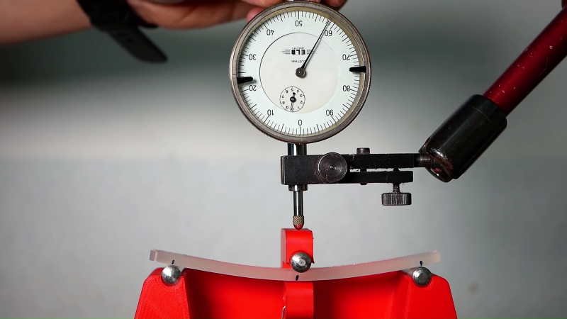
A 3D-printed bracket can look like a tiny bridge girder and still flex like a nervous ruler. That is why stiffness deserves its own measurement instead of being guessed from appearance, filament labels, or the highly scientific “bend it with your thumb” test.
Measuring the stiffness of 3D-printed parts means determining how much a specimen or finished component deforms under a known load. The basic idea is simple. The execution is not, because additive manufacturing turns material, geometry, print direction, infill, walls, temperature, moisture, and post-processing into one complicated mechanical casserole. A useful test must separate those influences, control them, and report enough detail for someone else to reproduce the result.
What Stiffness Really Means
Stiffness describes resistance to elastic deformation. A stiff object changes shape only slightly when loaded and returns to its original form when the load is removed. It is easy to confuse stiffness with strength, but they answer different questions. Stiffness asks, “How far will it bend?” Strength asks, “How much load can it survive before yielding or breaking?” A part can be stiff and brittle, flexible and strong, or inconveniently bad at both.
Material Stiffness Versus Part Stiffness
Young’s modulus, usually written as E, is a material property obtained from the slope of the initial linear portion of a tensile stress-strain curve:
E = change in stress / change in strain
Stress is load divided by original cross-sectional area, while strain is the change in gauge length divided by the original gauge length. Because strain has no units, modulus is reported in units of stress, commonly megapascals or gigapascals.
Component stiffness is different. It is often written as k = F/δ, where F is load and δ is deflection. Component stiffness depends on material modulus and geometry. Double the thickness of a beam and its bending behavior may change dramatically, even though the polymer itself has not become magically more athletic.
For printed products, both values matter. Young’s modulus helps with material models and comparisons. Part stiffness tells you whether the actual clamp, arm, enclosure, fixture, or robot finger will perform its job.
Why 3D-Printed Parts Need Special Treatment
A molded plastic coupon is usually treated as a reasonably uniform material. A material-extrusion print is closer to a manufactured laminate composed of roads, layers, interfaces, air gaps, and outer shells. Its stiffness may therefore vary with direction.
Build Orientation and Raster Direction
Loads applied along deposited roads are carried differently from loads that try to separate layers. This anisotropy is especially important in fused filament fabrication. A specimen printed flat, on edge, or vertically may produce different modulus and failure results even when the CAD file and filament spool are identical.
Infill, Walls, and Internal Architecture
Infill density affects stiffness, but it is not the whole story. In bending, material farthest from the neutral axis contributes heavily to rigidity, so additional perimeters or thicker skins can be more effective than simply stuffing the center with infill. Pattern, raster angle, overlap, air gaps, and whether infill bonds properly to the shell also matter.
Process Quality
Nozzle temperature, extrusion rate, cooling, chamber temperature, layer height, bead width, speed, and filament condition influence bonding and porosity. A nominally identical print made with under-extrusion or weak layer fusion is not mechanically identical. It is merely wearing the same CAD costume.
Environment and Post-Processing
Polymers are sensitive to temperature, loading duration, and sometimes humidity. Nylon can absorb moisture and change behavior. Thermoplastics can creep under sustained load. Photopolymer parts may not reach their intended mechanical properties until washing and post-curing are complete. Consequently, test specimens should be conditioned and tested under controlled, documented conditions.
Four Practical Ways to Measure Stiffness
1. Tensile Testing for Young’s Modulus
A tensile test is the standard choice when the goal is an engineering modulus for material comparison or simulation. Printed dog-bone specimens are gripped in a universal testing machine and pulled at a controlled rate. Load and strain are recorded, producing a stress-strain curve.
For plastic coupons, ASTM D638 is a common reference method. The critical detail is strain measurement. Crosshead travel includes grip movement, frame compliance, and possible slipping, so it can make the specimen appear more flexible than it truly is. A contact extensometer, video extensometer, or digital image correlation system provides better gauge-length strain data.
Print coupons in every direction relevant to the application. At minimum, identify build orientation, road direction, layer height, material batch, nozzle and bed settings, wall count, infill, post-processing, and conditioning. Reporting “PLA, 2 GPa” without those details is less a test result and more a rumor.
2. Three-Point Bending for Flexural Modulus
Flexural testing is often convenient for stiff plastics, short specimens, and parts primarily loaded in bending. A rectangular bar rests on two supports while a loading nose pushes at the center. The slope of load versus deflection is used to calculate flexural modulus, commonly following ASTM D790.
Span length, specimen width, thickness, loading rate, support geometry, and the method used to measure deflection all influence the answer. Thickness deserves special attention because beam rigidity scales strongly with its cube. A small measurement error can become a surprisingly large modulus error.
3. Compression and Dynamic Mechanical Testing
Compression testing is useful for lattice cushions, spacers, cellular structures, and parts whose real duty is being squeezed rather than stretched. Dynamic mechanical analysis goes further by measuring stiffness as temperature or loading frequency changes. That is valuable for polymers used near heat sources, in vibrating equipment, or across a wide operating-temperature range.
4. Application-Specific Part Testing
Coupon tests cannot capture every fillet, bolt hole, seam, lattice, insert, or local stress concentration. For a production component, build a fixture that reproduces its actual supports and load path. Apply a known force and measure displacement at the functional point.
This test produces component stiffness rather than a universal material modulus, but that may be exactly what the design requires. A camera with a scale, a dial indicator, a displacement sensor, or a test machine can measure movement. The fixture itself must be much stiffer than the part or its compliance must be measured and subtracted.
A Repeatable Testing Workflow
Define the Engineering Question
Start with a performance statement: “The arm must deflect less than 1 millimeter under 40 newtons,” or “The printed material model needs tensile modulus in the X, Y, and Z directions.” This determines whether to test coupons, finished parts, or both.
Design a Controlled Experiment
Change one important variable at a time unless you are using a formal design of experiments. Print several replicates for each condition; five specimens per condition is a practical starting point for development work, though applicable standards or quality plans may require a different sample count.
Randomize build positions when possible. Parts near different locations on a build plate can experience different cooling or process behavior. Keep filament or resin lot, machine, slicer version, profile, and post-processing constant. Save the project file rather than relying on screenshots and memory.
Condition and Measure Specimens
Store specimens in the intended test environment long enough to stabilize. Record temperature and relative humidity. Measure width and thickness at multiple points using suitable tools, because printed surfaces are not perfectly smooth and nominal CAD dimensions may not represent the load-bearing section.
Run the Test Carefully
Align the specimen to avoid unintended bending or torsion. Use an appropriate load cell so the measured forces occupy a useful portion of its range. Apply a small seating load if the method permits, then test at a controlled rate. Watch for grip slip, support indentation, crushing, layer separation, and failure outside the intended gauge region.
Calculate and Report Honestly
Calculate modulus from the prescribed strain interval or regression range rather than selecting the prettiest-looking slope. Report the mean, standard deviation, specimen count, and individual results. Include photos of fracture surfaces or deformation modes. An average without scatter can hide the fact that three specimens behaved well and two apparently received career advice from a potato chip.
A Simple Cantilever Example
Suppose a printed rectangular beam is clamped as a cantilever. Its free length is 80 millimeters, width is 10 millimeters, thickness is 4 millimeters, and a 5-newton load produces 4 millimeters of tip deflection. For a slender beam with small elastic deflection:
δ = F L³ / (3 E I)
I = b h³ / 12
The second moment of area is 53.3 mm4. Rearranging the first equation gives an estimated modulus of about 4,000 N/mm2, or 4 GPa. This is only valid when the clamp is rigid, dimensions are accurate, deflection is elastic, and beam assumptions are reasonable.
Repeat the measurement at several low loads. A linear load-deflection plot is a good sign; a curve or permanent bend means the simple elastic model is no longer telling the whole story.
How to Interpret the Results
Do not compare numbers unless the tests are genuinely comparable. Tensile modulus, flexural modulus, dynamic storage modulus, and finished-part spring rate are related but not interchangeable. Manufacturer data can be useful, yet printed properties depend on the stated printer, orientation, curing cycle, specimen geometry, and environmental condition.
The most valuable result is often not the highest modulus. It is the combination of stiffness, mass, repeatability, print time, cost, impact behavior, and durability that meets the application. A 100-percent-infill part may be stiffer, but a redesigned shell with ribs can achieve better rigidity with less material and fewer hours spent listening to stepper motors perform experimental music.
Conclusion
Measuring the stiffness of 3D-printed parts requires more than loading a sample and copying a number from software. Choose a test that matches the design question, measure strain or deflection accurately, control print and environmental variables, test relevant orientations, use multiple specimens, and report the full process.
For material characterization, tensile or flexural testing provides standardized modulus values. For design validation, application-specific fixtures reveal how the real part behaves. Used together, these methods replace guesswork with evidence and turn a promising print into a defensible engineering component.
Practical Testing Experience: Lessons That Save Time
The following lessons reflect common laboratory and prototyping practice when teams begin measuring printed-part stiffness. The first surprise is that the test machine is rarely the biggest source of confusion. The print itself usually wins that contest.
First, establish a baseline coupon before testing clever geometry. Ribs, lattices, curves, and topology-optimized shapes can improve performance, but they also make it harder to identify why a part changed. A simple tensile bar or rectangular flexural coupon reveals whether a new material batch, orientation, or process setting altered the underlying response. Once that baseline is stable, complex components become easier to diagnose.
Second, do not assume more infill automatically fixes bending. In practical beam and bracket tests, increasing shell thickness often produces a more efficient stiffness gain because the outer material carries much of the bending stress. Infill still supports skins, resists local buckling, and transfers load, but a dense center cannot rescue thin, poorly bonded walls from every design mistake. Testing wall count and infill as separate variables usually teaches more than jumping directly from 20 percent to 100 percent infill.
Third, measure the fixture. A cantilever clamp can rotate slightly, a printed test jig can flex, and a bench can move. Those tiny motions are included in the measured displacement unless they are independently checked. One practical method is to replace the specimen with a thick metal reference, apply the same load, and record fixture movement. If the fixture deflects 0.3 millimeter while the printed part appears to move 1.0 millimeter, ignoring compliance creates a large error.
Fourth, mark the gauge section and record video. A simple contrasting dot pattern helps reveal local strain, grip slip, and where deformation begins. Video also captures the moment layers whiten, separate, or buckle. Load data may say “something changed at 420 newtons.” The footage may say “the left grip slipped because someone tightened it with the enthusiasm of a sleepy librarian.”
Fifth, repeat tests on different days. A process that looks wonderfully consistent in one afternoon may drift after a nozzle change, a wet filament weekend, a new resin bottle, or a different curing cycle. Repeating a reference condition is an inexpensive way to detect machine and material drift. Reference coupons are especially useful when a shop has several printers that supposedly share the same profile.
Sixth, test the expected service temperature. A bracket that is impressively stiff in an air-conditioned room may soften near a motor, inside a vehicle, or under sunlight. Likewise, a part under constant load may creep even when a short test looked excellent. A useful development plan includes room-temperature modulus, elevated-temperature deflection, and a sustained-load check when the application demands dimensional stability.
Finally, preserve failed specimens. Label them with orientation, settings, and test number. Fracture location and surface appearance often explain scatter better than a spreadsheet. Clean layer separation suggests a different problem from ductile stretching, shell buckling, or failure around an internal void. A box of well-labeled failures may not look glamorous, but it is one of the fastest routes to better print settings and smarter designs.