

A conventional digital display quietly lights a few LEDs and gets on with its day. An electromagnetic 7-segment display takes a more theatrical approach. It moves real physical pieces, announces every update with a crisp mechanical click, and continues showing its number after the driving current stops. It is part display, part kinetic sculpture, and part tiny percussion instrument.
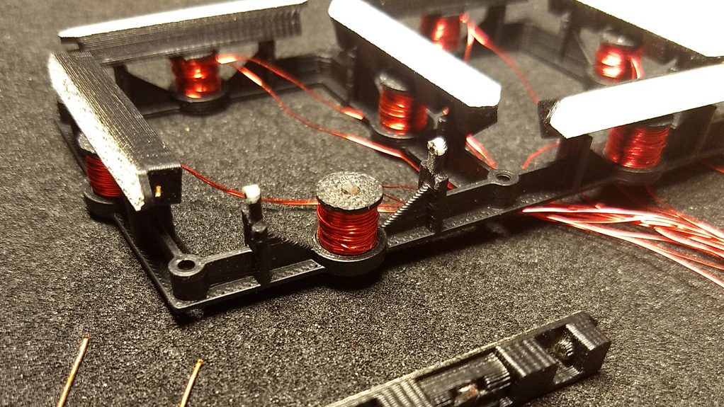
Designer Nicolas Kruse demonstrated this idea with a 3D-printed, magnetically actuated single-digit prototype. Each of its seven segments contains a small permanent magnet. Electromagnetic coils behind the face push or pull those segments into position, forming the familiar digits from zero through nine. The result combines the instant readability of a digital numeral with the personality of old transportation signs, electromechanical counters, and machines that sounded busy because they genuinely were.
What Is an Electromagnetic 7-Segment Display?
A 7-segment display forms numbers using seven bar-shaped elements arranged in a figure-eight pattern. By activating different combinations, the display can produce all ten decimal digits and a limited selection of letters. The format is familiar because it appears on clocks, calculators, meters, appliances, scoreboards, and enough alarm clocks to have ruined Monday mornings for several generations.
Most modern 7-segment modules use LEDs or LCD elements. Kruse’s version replaces illuminated segments with physical flaps. A visible side faces forward when a segment is active, while the darker or hidden side blends into the background when it is inactive. Instead of generating light, the display reflects ambient light.
From Electronic Symbol to Physical Movement
The basic number patterns remain unchanged. A zero uses every segment except the center bar. A one uses the two right-side segments. An eight activates all seven. The difference is that each command must create mechanical motion rather than merely switch a diode on.
That motion is what gives the display its unusual appeal. The observer does not simply see a new digit appear. The segments physically rotate, strike their stops, and settle into a new arrangement. Updating the display becomes a visible event rather than an invisible change in current.
How the Electromagnetic Mechanism Works
Small Magnets Inside the Segments
Kruse’s prototype places a small neodymium disk magnet inside each printed segment. Behind every segment is a hand-wound electromagnetic coil containing an iron core. When current flows through a coil, the resulting magnetic field interacts with the permanent magnet and flips the segment.
Reverse the polarity of the magnetic field, and the segment moves in the opposite direction. This two-way actuation allows the controller to expose or hide any segment without relying on gravity, springs, or a continuously running motor.
Iron Cores Concentrate the Magnetic Field
The coils use iron cores to concentrate magnetic flux near the segment magnets. In Kruse’s design, the iron also helps hold the segments in their most recent positions after current stops flowing. The stored magnetic behavior of the core provides enough attraction to prevent the flaps from casually wandering around whenever somebody closes a nearby door with enthusiasm.
This ability to remain in either of two stable positions is commonly described as bistability. Commercial electromagnetic 7-segment modules use a related principle: a short current pulse changes the magnetic state, and the reflective segment remains set or reset until another pulse arrives.
Fast Pulses Instead of Continuous Power
The prototype drives its coils with software-controlled pulse-width modulation at a peak current of roughly 1.6 amps and a duty cycle near 50 percent. At that drive level, a segment can flip reliably in less than 10 milliseconds. The controller actuates the segments one after another rather than firing all seven simultaneously, reducing the peak demand placed on the power supply.
That sequential behavior can add a subtle rolling quality to a digit change. The full update is still quick, but the movement has a rhythm. It looks less like a screen refresh and more like a tiny machine making a decision.
The Electronics Behind the Clicking
An ATtiny44 Coordinates the Display
The original controller uses an ATtiny44 microcontroller with N-channel and P-channel MOSFETs to direct current through the coils. The ATtiny44A family includes timer and PWM capabilities, making it suitable for producing controlled pulses without requiring a large processor or an operating system that needs three updates before it can display the number four.
The microcontroller receives or generates a numeral, translates it into a seven-segment pattern, compares that pattern with the display’s current state, and pulses only the segments that need to move. Avoiding unnecessary flips reduces noise, power use, heat, and mechanical wear.
Why MOSFETs Are Necessary
A microcontroller pin cannot safely provide the current demanded by an electromagnetic coil. MOSFETs act as electronic switches between the logic circuitry and the higher-current actuator supply. Because the direction of current determines the direction of movement, the driver must also be able to reverse coil polarity or otherwise create opposite magnetic fields.
Coils are inductive loads, so switching them off can create a voltage spike. A reliable driver needs suitable suppression, such as flyback diodes, transient-voltage devices, or a carefully designed recirculation path. SparkFun’s solenoid-control guidance likewise recommends protective diode arrangements for long-term MOSFET reliability.
The Passive Matrix Problem
Kruse initially intended the driver to control a passive matrix of four digits by seven segments. Matrix wiring can reduce the number of control connections, much as multiplexing simplifies many LED displays. Adafruit notes that ordinary multi-digit LED matrices commonly rely on multiplexing and dedicated driver chips to avoid an inconvenient forest of wires.
The electromagnetic version introduces a harder problem. In the prototype matrix, neighboring segments received roughly half the intended current. That partial drive was sometimes strong enough to disturb a segment that was supposed to remain still. LEDs tolerate clever scanning because they have no mechanical threshold. A magnetic flap has friction, inertia, attraction, and a tendency to interpret “half a command” as “perhaps I should ruin this clock.”
For a single digit, the circuit worked well. Scaling it to a multi-digit display would require better isolation, individual drivers, improved coil geometry, a different matrix strategy, or tighter control of the magnetic switching threshold.
Why the Display Is Easy on the Eyes
It Reflects Light Instead of Producing It
An electromagnetic display does not need to shine directly at the viewer. The active faces of its segments reflect room light or sunlight, while the inactive state blends into a contrasting background. Commercial modules use light-colored, UV-resistant segments against matte black backgrounds for visibility across a wide range of ambient conditions.
This is especially attractive in bright environments. Emissive displays can lose apparent contrast when ambient light raises the visible black level or introduces glare. NIST display research notes that ambient illumination can reduce contrast and impair readability on emissive systems. A well-designed reflective segment, by contrast, can become easier to see as more light reaches it.
No Optical Refresh Is Needed While the Number Is Static
Once the physical segments settle, the image is simply there. It is not being recreated through rapid multiplexing, backlight modulation, or continuous pixel refresh. The display behaves more like printed signage that happens to rearrange itself.
This does not automatically make every mechanical display medically superior to every electronic screen. Readability still depends on segment size, color, contrast, viewing angle, reflections, and illumination. However, the absence of a glowing panel and the stability of the physical image can make the display visually calm and comfortable in clocks, counters, dashboards, and decorative installations.
Why It Is Also Easy on the Ears
“Easy on the ears” does not mean silent. Quite the opposite. Each moving segment produces an audible click as it reaches its stop. A complicated digit transition may create a quick cluster of clicks, while a minor update may produce only one or two.
The sound becomes useful feedback. You can hear that the command was received and that something moved. Audio-tactile interface research has explored how combined sensory cues can make interactions feel more definite and engaging. In this display, the sound is not added by a speaker. It is an honest byproduct of the mechanism doing its job.
The clacking also creates emotional character. Silent electronics tend to hide their effort. Mechanical displays reveal it. A clock built from several digits could create a satisfying burst at the top of every minute, although placing one beside a light sleeper may eventually test the outer limits of domestic diplomacy.
Building the Mechanical Structure
3D Printing Makes Repeated Parts Practical
A seven-segment digit contains many similar components: seven flaps, seven coil supports, seven pivots, and a frame that keeps everything aligned. That repetition makes the design well suited to 3D printing. Kruse released printable files for the base, segments, and coil spools, along with the driver design and firmware.
The printed parts still require careful finishing. In the prototype, the segment axle bores were finished with a 0.5-millimeter drill. Tiny pivot holes can shrink, roughen, or become slightly oval during printing, and even a small amount of friction may prevent a coil pulse from producing reliable motion.
Alignment Matters More Than Brute Force
A common temptation is to solve unreliable movement by increasing the current. That approach can work briefly, right before it turns the coil into a hand warmer. Better results usually come from reducing friction, positioning the magnet accurately, centering the iron core, balancing the flap, and ensuring that mechanical stops do not bind.
Magnetic spacing is particularly sensitive. A gap that is too large weakens the force. A gap that is too small may cause the segment to cling to the core or collide with the surrounding structure. Recent miniature flip-display experiments have also found that magnet orientation and interaction between adjacent segments can strongly influence reliability.
Power Consumption: Low Overall, High for an Instant
The display’s power behavior is unusual. During a flip, a coil may draw substantial current. Between updates, however, the mechanism can hold its state without continuous coil power. For applications that change only occasionally, average energy use can therefore remain modest.
This resembles the advantage of electronic paper: energy is concentrated during an update, while a static image persists afterward. DigiKey describes reflective e-ink displays as readable in bright light and highly efficient for mostly static information because the image remains stable without continuous power. An electromagnetic display reaches a similar destination through moving plastic and magnets rather than charged pigment particles.
The power supply must still handle the instantaneous current safely. Sequential actuation, local energy-storage capacitors, current monitoring, fusing, and conservative thermal design become increasingly important as more digits are added.
How It Compares With Other Display Technologies
Compared With LED 7-Segment Displays
LED modules are inexpensive, compact, fast, widely available, and easy to control with dedicated drivers. They are the obvious choice for most appliances and instruments. Electromagnetic modules are larger, more mechanically complex, and more demanding to manufacture.
However, LEDs require power to remain illuminated, while bistable mechanical segments can preserve a static reading. LEDs also look like electronic components. Electromagnetic segments look like objects. That distinction matters in art installations, retro equipment, public signage, custom clocks, and products where personality is part of the specification.
Compared With E-Ink
E-ink offers far greater graphic flexibility, higher information density, and silent operation. An electromagnetic 7-segment display offers faster physical movement, bold numerals, a visible mechanism, and an audible event. E-ink whispers. The flip display clears its throat and enters the room.
Compared With Split-Flap and Flip-Dot Displays
Split-flap displays rotate through sets of complete printed characters. Flip-dot displays use many small bistable disks to form text or graphics. An electromagnetic 7-segment design occupies the middle ground: fewer moving parts than a dot matrix, faster direct access than a large split-flap wheel, and enough segments to show numeric information clearly.
Commercial electromagnetic seven-segment modules have been used in fuel-price displays, portable measuring equipment, scales, and toll systems, where sunlight visibility and retained state are valuable.
Where This Display Could Be Used
The most obvious application is a clock, especially one mounted in a workshop, studio, café, or living room where the clicking becomes part of the atmosphere. Other possibilities include countdown timers, queue counters, production totals, scoreboards, departure displays, art pieces, escape-room props, interactive exhibits, and physical dashboards for online statistics.
A connected version could pair the electromechanical digit with an ESP32 or similar controller. The network processor could retrieve time, weather data, subscriber counts, energy consumption, or sensor readings, while a dedicated driver board handles the high-current magnetic pulses.
The best applications are those in which information changes occasionally rather than dozens of times per second. Nobody needs an electromagnetic segment display for streaming video unless the goal is to build the world’s loudest and least successful television.
A Maker’s Experience: What Building One Teaches You
The first surprise in a project like this is how quickly it stops being “just an electronics build.” On the schematic, the concept looks wonderfully clean: energize a coil, move a magnet, display a number. On the workbench, every segment develops a personality. One flips decisively. Another hesitates. A third works perfectly until the frame is tightened, at which point it apparently joins a labor union.
Mechanical tuning becomes the real center of the experience. A builder may spend more time sanding pivot pins, clearing printed holes, adjusting clearances, and repositioning magnets than writing firmware. The lesson arrives early: software can command a movement, but it cannot negotiate with a flap that is physically jammed.
Coil winding is similarly educational. Each spool must be reasonably consistent so that the segments respond to similar pulse lengths and currents. Too few turns may produce a weak magnetic field. Too many turns may increase resistance and reduce current. Loose winding wastes space, while overly aggressive winding can damage thin enamel insulation. By the seventh coil, the builder usually understands why factories use winding machines and why those machines deserve a polite nod of respect.
The first successful flip is the project’s magic moment. A brief pulse reaches the driver, the coil field rises, and the segment snaps into view. It feels more substantial than lighting an LED because energy has crossed from code into visible movement. The click confirms the result before the eyes finish processing it.
The next phase is less magical but more useful: repeatability testing. A segment should not merely flip once for a camera. It should change state hundreds or thousands of times without sticking, overheating, loosening its axle, or responding to a neighboring coil. Repeated cycles reveal rough pivot surfaces, weak adhesive, inconsistent magnetic gaps, undersized transistors, and pulse durations that were selected with optimism rather than measurement.
Sound also becomes a design variable. A rigid plastic frame produces a sharp click. Softer stops reduce noise but may absorb too much energy or make the final position less precise. Mounting the display in a hollow enclosure can amplify each movement like a tiny drum. A solid backing plate may lower the pitch. Builders who begin by saying, “The noise is part of the charm,” may later find themselves testing felt pads at midnight.
Power testing teaches another important lesson. The average current may appear low because pulses are brief, yet the instantaneous current can cause supply voltage dips, microcontroller resets, hot MOSFETs, or noisy signals. Adding bulk capacitance, separating logic and actuator power paths, improving grounding, and actuating one segment at a time can transform an unreliable prototype into a dependable machine.
The finished display rewards that effort. It looks readable when unpowered, changes with physical confidence, and attracts attention without needing animated graphics. People instinctively lean closer because the mechanism is understandable. They can see the segment, hear the click, and imagine the magnet and coil behind it. The project turns an ordinary numeral into a performanceand reminds the builder that sometimes the most memorable interface is not the one with the most pixels, but the one that moves seven small pieces exactly where they belong.
Conclusion
The electromagnetic 7-segment display succeeds because it combines several technologies that are individually simple but collectively delightful. Seven printed flaps create the numeral. Permanent magnets and iron-cored coils provide the movement. MOSFETs handle the current. A small microcontroller times the pulses. Bistable behavior preserves the image, reflective surfaces keep it legible, and every update arrives with its own mechanical soundtrack.
It will not replace the humble LED module, nor should it. Its purpose is different. This is a display for projects in which motion, sound, craftsmanship, and visible engineering matter as much as the number itself. It is proof that digital information does not have to live behind glass. Sometimes it can flip, click, and proudly remain exactly where it was told.
Note: Electromagnetic coils can draw high pulse currents and generate damaging switching transients. Builders should verify component ratings, include suitable circuit protection, monitor coil temperature, and keep small magnets away from children, magnetic storage media, and sensitive medical devices.