Every so often, the hardware world produces a project that makes experienced engineers lean toward the screen, squint, and whisper, “Surely that cannot be legal.” Not illegal in the criminal sense, of course, but illegal in the “my soldering iron just packed its bags and left” sense. Incredible soldering in the name of hardware support is exactly that kind of story: a reminder that behind smooth open-source tools, polished hardware boards, and friendly documentation, there is often one brave person doing something tiny, risky, and slightly unhinged with molten metal.
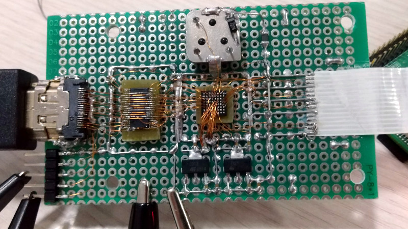
The phrase comes from a famously jaw-dropping hardware experiment involving Pi-KVM, a Raspberry Pi-based KVM-over-IP project, and the Toshiba TC358743 HDMI-to-CSI bridge chip. The goal was not to create soldering art for a museum, although the result arguably qualifies. The goal was practical: understand the hardware deeply enough to improve support, reduce latency, and make remote server management better. In plain English, someone hand-soldered a tiny BGA chip into a working video-capture prototype so the rest of us could eventually plug in something neat and say, “Wow, that was easy.”
This article explores why that work matters, what makes BGA soldering so intimidating, how hardware support benefits from hands-on experimentation, and what makers, repair technicians, and engineers can learn from this tiny-but-mighty act of electronics bravery. Bring flux. Bring patience. Bring a microscope if you have one. Your dignity may or may not survive.
What Makes This Soldering So Incredible?
Most soldering projects are simple enough to explain at a dinner table without frightening anyone. You heat a pad, add solder, attach a wire, and try not to brand your finger like a careless cowboy. Through-hole soldering is friendly because the component leads pass through the board. Surface-mount soldering is fussier, but many SMD parts still have visible leads or pads. You can see what you are doing, which is a luxury humans tend to enjoy.
Ball grid array, or BGA soldering, is different. A BGA chip has its connections underneath the package in the form of tiny solder balls. Once the chip is placed, the actual joints are hidden. In normal manufacturing, BGA components are mounted using solder paste, controlled heat profiles, reflow ovens, inspection tools, and often X-ray equipment. It is less “hold this with tweezers” and more “please consult the thermal gods.”
The Pi-KVM-related experiment was remarkable because it pushed this idea into hand-built territory. The Toshiba TC358743 chip, commonly used as an HDMI-to-MIPI CSI-2 bridge, is not a friendly DIP package from a beginner electronics kit. Yet it was hand-connected into a functional capture device using tiny wires and improvised board material. The result reportedly handled 1080p video signals, which is the kind of sentence that makes hardware people both impressed and mildly offended.
The Hardware Support Problem: Documentation Is Never Enough
Hardware support is not just about reading a datasheet and writing cheerful code. Datasheets can be incomplete, confusing, outdated, or guarded like ancient treasure maps. Even when the document is available, real hardware has quirks. Timing matters. Signal integrity matters. Power sequencing matters. The board layout matters. That one capacitor you thought was optional may, in fact, be the tiny bouncer keeping chaos out of the club.
For Pi-KVM, the broader mission is practical: allow users to control computers remotely at a very low level, including BIOS access, operating system installation, power control, and keyboard-video-mouse interaction. A KVM-over-IP tool needs reliable video capture, low latency, and predictable behavior. USB HDMI capture dongles can work, but a CSI-connected HDMI capture path can reduce overhead and improve responsiveness. That is why understanding a chip such as the TC358743 is not just academic curiosity. It directly affects how well users can manage servers, troubleshoot machines, and recover systems when everything else has gone sideways.
This is where “incredible soldering” becomes more than a stunt. The soldering was a means to an end: build a rough but functional test platform, observe the chip closely, experiment with configuration, and gather knowledge that could feed a cleaner dedicated board later. Hardware support often advances through this messy middle stage. The finished product may look elegant, but the prototype usually looks like it fought a raccoon and won on points.
Why Pi-KVM Needed Better Video Capture
Pi-KVM is popular because it turns inexpensive, flexible hardware into a powerful remote-management tool. Instead of depending on proprietary enterprise KVM boxes, users can build or buy a Raspberry Pi-based device that provides browser-based control of another computer. For homelab owners, system administrators, hardware developers, and people who enjoy rescuing headless machines at 2 a.m., this is extremely useful.
Video capture is one of the key pieces. If the remote display has lag, dropped frames, poor compatibility, or unreliable detection, the entire experience suffers. Imagine trying to enter BIOS settings while the screen updates like a sleepy slideshow. That is not remote administration; that is a patience-themed escape room.
The Raspberry Pi’s CSI connector was originally designed for camera input, but with the right bridge hardware, HDMI video can be converted into a format the Pi can ingest efficiently. MIPI CSI-2 is widely used for high-speed image transfer from cameras and imaging devices to processors, so it is a natural fit for low-latency video paths when implemented correctly. The challenge is that “implemented correctly” is doing a lot of heavy lifting. You need electrical compatibility, suitable drivers, proper initialization, and a board design that does not turn high-speed signals into interpretive dance.
The Toshiba TC358743: Small Chip, Big Responsibility
The Toshiba TC358743 is an HDMI-to-CSI bridge chip. In a Pi-KVM-style setup, its job is to accept HDMI input and output video over a CSI-2 interface. Conceptually, this sounds tidy: HDMI goes in, CSI comes out, everyone applauds politely. In practice, bridge chips often require careful configuration, register-level understanding, and attention to how the host system expects video data.
When documentation is thin or scattered, developers sometimes have to learn by building, probing, testing, and breaking things in controlled ways. That is exactly why a scratch-built capture device can be valuable. A homemade board gives the developer visibility into the chip’s behavior, power rails, signal routing, and failure modes. It is not as pretty as a factory PCB, but it is honest. It will tell you when you are wrong, usually by refusing to work until midnight.
That kind of work is the foundation of good hardware debugging. The developer is not merely soldering for spectacle. They are creating an experimental platform that answers questions no marketing page can answer. Does the chip initialize as expected? What settings improve latency? Which capture modes are stable? How does the Raspberry Pi handle the data? Which compromises are acceptable for DIY users?
BGA Soldering: Why Hidden Connections Raise the Stakes
With visible leads, bad solder joints are often obvious. A bridge looks like a tiny silver blob connecting two pins that should not be friends. A cold joint looks dull or cracked. A missing joint is simply not there, standing in the corner wearing a sign that says, “I forgot my job.”
With BGA, many defects are hidden underneath the package. A solder ball might not wet properly. Two balls might bridge. The chip might be slightly misaligned. Heat might be uneven. The board might warp. Without inspection tools, diagnosing the issue becomes part electronics, part detective story, and part emotional support exercise.
That is why hand-wiring a BGA-style device is so impressive. It bypasses the normal PCB escape-routing challenge by manually connecting tiny points, but it introduces its own difficulties: wire length, wire strain, solder joint strength, parasitic capacitance, impedance mismatch, and plain old hand tremor. At high video data rates, messy wiring can become a signal-integrity nightmare. The fact that such a build can function at all is a tribute to persistence, planning, and possibly excellent caffeine management.
Flux, Heat, and the Fine Art of Not Making a Tiny Disaster
Good soldering is often described as a three-part relationship between heat, metal, and cleanliness. The solder must flow, the surfaces must wet, and the joint must cool without movement. Flux helps by removing oxidation and improving wetting. Temperature control keeps the process from becoming either too cold to bond or hot enough to bully nearby components into retirement.
For electronics soldering, rosin-based and no-clean fluxes are common. Extra flux can make difficult joints dramatically easier, especially when dealing with small pads, oxidized surfaces, or rework. However, flux is not magic gravy. Too much can cause residue problems, slow heating, or encourage bridges in tight spaces. The goal is controlled assistance, not dipping the board like a breadstick.
Tool choice also matters. A fine conical tip can reach tiny joints, but a small chisel or hoof tip may transfer heat more effectively. Tweezers, magnification, brass wool, desoldering wick, and a stable work holder are not luxuries; they are what prevent the bench from becoming a parts confetti launcher. For serious micro-soldering, a stereo microscope changes everything. Once you can actually see the joint, your success rate improves and your vocabulary becomes less colorful.
Hardware Support Is Built on Ugly Prototypes
One of the most important lessons from this story is that ugly prototypes deserve respect. In software, a prototype may be a rough script. In hardware, a prototype may be a perfboard creature with wires going everywhere and just enough structural integrity to survive one more test. It may look like a cyberpunk bird’s nest, but it carries knowledge.
Professional hardware eventually wants proper PCB layout, impedance-controlled traces, power filtering, ESD protection, test points, and manufacturability. But before that, someone has to prove the concept. Someone has to make the chip talk. Someone has to determine whether the idea is worth turning into a real board. That is the role of experimental soldering.
In the Pi-KVM case, the handmade HDMI capture experiment helped bridge the gap between “this chip should work” and “we understand it well enough to support better hardware.” That distinction matters. Good open-source hardware is not only about releasing files. It is about reducing mystery for the next person. The best support comes from people who have already walked through the swamp, mapped the mud, and labeled the alligators.
Specific Lessons for Makers and Repair Technicians
1. Start With the Purpose, Not the Flex
Incredible soldering is fun to admire, but the best projects begin with a reason. In this case, the reason was better hardware support and lower-latency video capture. Before attempting a difficult soldering job, ask what knowledge or capability it unlocks. If the answer is “internet points,” that is valid but perhaps expensive in replacement components.
2. Respect the Package
Through-hole, SOIC, QFP, QFN, and BGA packages each demand different techniques. BGA parts are usually not ideal for casual hand soldering because the joints are hidden. When possible, use breakout boards, development kits, or professionally fabricated PCBs. When not possible, accept that you are entering advanced territory and prepare accordingly.
3. Build a Better Workbench Before Blaming Your Hands
Many soldering failures are really setup failures. Poor lighting, a dirty tip, no flux, unstable workholding, and bargain-bin solder can make even simple joints miserable. A decent iron, good flux, clean tips, ventilation, and magnification do not make you instantly skilled, but they remove unnecessary suffering. Electronics already supplies enough suffering for free.
4. Test in Stages
Do not solder an entire complex build and then wonder which of 200 connections is guilty. Check power rails first. Verify continuity. Inspect for shorts. Bring up subsystems one at a time. Measure before connecting expensive boards. A multimeter is cheaper than replacing a Raspberry Pi because optimism briefly became your test plan.
5. Document the Messy Middle
Finished projects get the glory, but intermediate experiments often teach the most. Photos of wiring, notes about failed approaches, register settings, thermal observations, and unexpected compatibility issues can save other developers days of guesswork. Documentation is hardware support in written form.
The Safety Side: Fun Should Not Smell Like Burnt Regret
Soldering can be safe, but it deserves basic discipline. Work in a ventilated area, keep fumes away from your face, wear eye protection when clipping leads or using hot air, and treat every iron like it is hot until proven otherwise. Molten solder is tiny, shiny, and deeply committed to finding exposed skin.
Lead-based solder is still used by some hobbyists because it melts easily and behaves predictably, but it requires careful handling. Wash your hands after use, do not eat at the bench, and dispose of contaminated materials responsibly. Lead-free solder is common in commercial electronics and modern repair, but it often needs higher temperatures and better technique. Either way, clean habits matter.
Hot-air work adds another layer of caution. Airflow can blow tiny parts into another dimension. Excessive heat can damage connectors, lift pads, scorch boards, or melt nearby plastic. Shield sensitive areas when needed, use proper nozzles, and remember that “more heat” is not a troubleshooting philosophy. It is how legends become cautionary tales.
Why This Story Still Inspires Hardware People
The appeal of this soldering story is not only technical. It is emotional. Anyone who has built hardware knows the feeling of chasing a stubborn problem through datasheets, forum posts, code, schematics, and increasingly questionable bench experiments. Sometimes progress requires a clean PCB. Sometimes it requires a brave little monster made from wires and stubbornness.
That is why the phrase incredible soldering in the name of hardware support resonates. It captures the spirit of open hardware at its best: practical, curious, generous, and a little bit wild. The person doing the work did not merely want a trophy build. They wanted to understand a device well enough to make the ecosystem better.
In a world where many devices are sealed, glued, locked down, or treated as disposable, this kind of experimentation is refreshing. It says hardware can be understood. It can be improved. It can be supported by communities instead of hidden behind proprietary fog. And sometimes, yes, it can be persuaded to work with solder joints so tiny they make a grain of rice look like office furniture.
Experience Notes: What This Topic Teaches at the Workbench
Working around projects like this changes how you see electronics. At first, soldering feels like a manual skill: hold the iron, feed the solder, try not to sneeze at the critical moment. After a while, it becomes a way of thinking. Every joint is a tiny argument between design intent and physical reality. The schematic says two points are connected. The solder joint either agrees or it does not.
One practical experience that stands out is how often the “impossible” repair becomes possible after slowing down. Beginners tend to attack a board with urgency. Experienced technicians pause. They clean the area, add flux, inspect under magnification, check whether the pad is still attached, and decide whether heat, solder, wick, or simply patience is the next tool. The difference is not magic. It is rhythm.
Micro-soldering also teaches humility. A person may be excellent at through-hole soldering and still feel like a confused raccoon when facing a fine-pitch connector or a microscopic resistor. That is normal. The scale changes the game. Hand pressure matters. Breathing matters. Lighting matters. Even the stiffness of the iron cable can matter. Many successful repairs begin with rearranging the bench so the workpiece is supported and the hands can rest. The best soldering posture looks less like a heroic battle and more like a dentist carefully negotiating with a robot tooth.
Another lesson is that diagnostics beat drama. When a board fails after soldering, the temptation is to reflow everything immediately. Sometimes that works; often it creates new faults. A better approach is to measure. Is there a short to ground? Are the power rails present? Does the chip warm normally? Are reset and clock signals alive? Does the connector orientation match the pinout? The meter, logic analyzer, and oscilloscope are boring until they save four hours of guessing. Then they become beloved family members.
For hardware support, hands-on soldering experience builds empathy. A support engineer who has actually lifted a pad, cleaned flux from under a connector, or chased a bad ground through a prototype understands user problems differently. They know that “check your wiring” can mean twenty different things. They know that a photo of a board can reveal backwards headers, dull joints, bridged pins, and missing pull-ups. They also know when a design should be changed so users do not have to perform heroic soldering in the first place.
That may be the most valuable experience of all: incredible soldering should inspire better hardware, not become a permanent requirement. A wild prototype is beautiful because it proves what is possible. A mature board is beautiful because it makes that possibility repeatable. The soldering hero goes first so everyone else can follow safely, reliably, and with fewer tiny wires attempting escape.
Conclusion
Incredible Soldering In The Name Of Hardware Support is more than a catchy headline. It is a compact philosophy for the hardware world. Real support comes from real understanding, and real understanding often comes from bold experiments that look absurd until they work. The Pi-KVM-related BGA soldering example shows how deep technical curiosity can turn a difficult chip into a better-supported hardware path for remote management, lower-latency capture, and open-source infrastructure.
For makers, the lesson is not that everyone should immediately hand-wire a BGA chip on perfboard. Please do not make your weekend plans that spicy unless you know what you are doing. The lesson is that careful experimentation, good soldering technique, documentation, and respect for the physical details of electronics can push projects forward in ways polished product pages never reveal.
Great hardware support is built by people willing to investigate the awkward layer between theory and reality. Sometimes that layer is firmware. Sometimes it is signal timing. And sometimes it is a tiny solder joint hiding under a chip, silently deciding whether your whole project gets to live.
Note: This article is original, source-informed editorial content created for web publication. It avoids copied source text, citation placeholders, and unnecessary publishing artifacts.