Every Arduino project begins with optimism. You plug in a board, toss a few jumper wires onto a breadboard, upload a sketch, and suddenly the LED blinks like it just discovered electricity. Then the project grows. One sensor becomes three. A button arrives. A battery sneaks in. The breadboard starts looking like a bowl of electronic spaghetti, and one loose jumper wire can ruin an entire afternoon. This is where an Arduino rapid design board earns its tiny square of glory.
The idea behind a rapid design board is beautifully practical: keep the friendly Arduino development experience, but remove the repetitive chores that happen when a prototype becomes something closer to a real device. Instead of redesigning the same microcontroller support circuit again and again, a compact module can bring the brain, bootloader, voltage regulation, reset hardware, and usable I/O into one solderable package. The result is less “Where did that wire go?” and more “Look, my project actually fits in a case.”
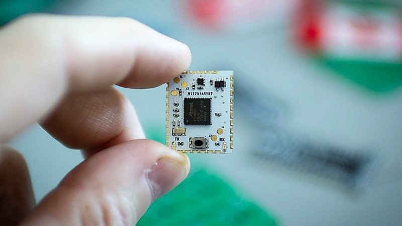
One clever example is the HCC Mod, an Arduino-compatible module built around the Microchip ATSAMD21G18 microcontroller. It was designed to bridge the gap between off-the-shelf development boards and custom PCBs. In plain English, it helps makers move from a clunky bench prototype to a neat board without having to become a full-time microcontroller-support-circuit detective.
What Is an Arduino Rapid Design Board?
An Arduino rapid design board is a prototyping shortcut for people who want the speed of Arduino development and the polish of a custom PCB. It is not just another Uno clone with headers sticking out like little plastic antlers. Instead, it is usually a compact module or carrier-friendly board that can be soldered directly into a larger design.
The HCC Mod takes this concept seriously. The name refers to its half-circle castellated connections, which are plated edge pads that let the module solder flat onto another PCB. Castellated modules are common in wireless boards, sensor modules, and compact embedded products because they save height, reduce loose wiring, and make assembly more repeatable. Think of it as the electronics version of replacing duct tape with actual screws.
For Arduino users, the appeal is simple. You can still write code in the familiar Arduino IDE, use common libraries, and build around the same beginner-friendly workflow. But when it is time to make the project permanent, the microcontroller no longer has to sit on a full development board that was never meant to live inside your finished enclosure.
Why the SAMD21 Makes Sense Here
The ATSAMD21G18 is a 32-bit ARM Cortex-M0+ microcontroller used in boards such as the Arduino Zero and many Adafruit Feather M0 models. It runs at up to 48 MHz and commonly appears with 256 KB of flash and 32 KB of SRAM, which is a comfortable step up from older 8-bit Arduino boards based on the ATmega328P.
That extra breathing room matters. More flash means more space for libraries, menus, sensor drivers, USB code, and the “temporary debug messages” that mysteriously become permanent. More RAM helps with buffers, displays, serial communication, and data handling. The SAMD21 also supports native USB, which can simplify programming and communication because the chip itself can handle USB functionality without relying on a separate USB-to-serial converter.
Another practical benefit is operating voltage. SAMD21 boards typically use 3.3 V logic, which plays nicely with many modern sensors, displays, radio modules, and low-power parts. That said, it also means designers must be careful with old-school 5 V components. A rapid board saves steps, but it does not grant diplomatic immunity from voltage mistakes.
The Problem With “Just Use an Arduino”
Using a full Arduino board in a final project is perfectly fine in many cases. If the box is large, the budget is relaxed, and nobody cares that the wiring looks like a tiny haunted forest, go forth and blink proudly. But several problems appear when the prototype needs to become smaller, sturdier, cheaper, or repeatable.
Development Boards Are Bigger Than the Final Circuit Needs
An Arduino Uno or Nano includes hardware that is wonderful for learning and testing but not always necessary in a finished product. Headers, USB connectors, power jacks, indicator LEDs, and extra layout space are convenient on the bench. Inside a wearable, handheld tool, custom controller, or sensor node, that same convenience can become wasted volume.
Breadboards Are Temporary by Nature
Solderless breadboards are fantastic for experiments, but they are not famous for surviving vibration, backpacks, curious cats, or “I only moved it one inch” accidents. Jumper wires can loosen. Contact resistance can vary. A circuit that worked last night may wake up grumpy for no obvious reason. Moving to a soldered board gives the project a much better chance of behaving like a product instead of a science fair drama.
Custom PCBs Require Repeating the Boring Bits
Designing a microcontroller circuit from scratch means adding power regulation, decoupling capacitors, reset circuitry, bootloader considerations, USB routing, clocking decisions, programming headers, and the correct footprint. None of that is impossible, but it is easy to make one tiny mistake that turns a beautiful PCB into a very flat coaster. A rapid design module bundles those known-good basics so the designer can focus on the project-specific circuit.
What the HCC Mod Brings to the Workbench
The HCC Mod was presented as an easy-to-solder Arduino and CircuitPython-compatible surface-mount module. Its purpose is not to replace every development board. Instead, it is meant to help makers who are ready to stop plugging wires into headers and start placing the microcontroller directly into their own PCB designs.
The original feature highlighted several useful traits: a SAMD21 microcontroller, 16 GPIO lines, six ADC inputs, an onboard 3.3 V regulator, and a reset button. That is enough for many compact projects: macro pads, sensor loggers, small robotics controllers, MIDI gadgets, LED controllers, homemade instruments, environmental monitors, and other devices that need a capable microcontroller without a full dev board bolted on like a backpack.
The open-source nature of the design is also important. Makers can inspect the files, learn from the layout, build compatible carrier boards, and adapt the concept to their own workflow. In the maker world, open hardware is not just a license badge; it is a classroom with copper traces.
Castellated Edges: Tiny Castle Walls With a Purpose
Castellated holes are plated half-holes along the edge of a PCB. They look a little like castle battlements, which explains the name and proves that even circuit-board terminology occasionally has medieval flair. Their purpose is simple: they let one board mount flat to another board while exposing solderable pads along the edge.
This matters because it creates a strong, low-profile connection. Instead of using tall pin headers, sockets, or flying wires, the module can be treated like a large surface-mount component. The carrier PCB supplies the surrounding circuitry, while the module supplies the proven microcontroller core.
Good castellated design still requires care. The carrier board should use a proper footprint, large enough pads for hand soldering, sensible spacing, and clear silkscreen orientation. Designers should also check the PCB manufacturer’s rules for plated half-holes, because minimum hole sizes, spacing, and edge plating requirements vary. This is not the place to assume “close enough” and then blame the soldering iron.
Where This Kind of Board Saves the Most Time
The strongest case for an Arduino rapid design board is repeated prototyping. If you build one simple project per year, a full Arduino board may be easier. But if you regularly design small gadgets, test interfaces, make custom controllers, or turn breadboard ideas into PCBs, the saved steps add up quickly.
Small-Batch Products
For a small run of custom devices, using a module can reduce design risk. Instead of laying out the SAMD21 and all supporting components every time, the designer can place the module footprint and route the project-specific connections. That can shorten the path from idea to prototype, especially when the product does not justify a fully optimized custom microcontroller layout yet.
Educational Projects
Students and workshop participants often understand Arduino code before they understand power integrity, USB routing, or microcontroller bootloaders. A rapid board lets them experience PCB design without throwing every advanced embedded-design challenge at them on day one. It is a bridge, not a crutch.
Wearables and Handheld Devices
Wearables and handheld projects punish bulky hardware. A castellated module can keep the controller compact while freeing the board shape to follow the enclosure, strap, grip, badge, or costume piece. Nobody wants a wearable that looks like it swallowed an Uno.
Control Panels and Macro Pads
The SAMD21’s USB capability makes it attractive for keyboards, macro pads, knobs, sliders, and human-interface devices. With a rapid design module, the PCB can focus on switches, encoders, LEDs, and mechanical layout while the module handles the microcontroller foundation.
How It Compares With Proto Shields and Perma-Proto Boards
Traditional Arduino prototyping shields are excellent for turning a one-off circuit into something more durable. A proto shield stacks on top of an Arduino and gives you solderable space for components. Perma-proto boards go a different direction: they mimic breadboard layouts on a solderable PCB, making it easier to transfer a circuit from temporary breadboard to permanent board.
An Arduino rapid design board serves a different purpose. It is not mainly a soldering area. It is the reusable microcontroller core for a custom PCB. In other words, a proto shield says, “Put your circuit on top of this Arduino.” A rapid design module says, “Put this Arduino-compatible brain inside your circuit.”
That distinction is subtle but powerful. Proto shields are great for bench-friendly builds and single modules. Castellated rapid boards are better when the final shape, size, and layout matter. If the enclosure is part of the design, the rapid board often wins.
Design Tips Before You Send the PCB Order
A rapid design board saves work, but it does not remove the need for careful design. Before sending Gerbers to a board house, check the module footprint, pin mapping, power rails, and programming path. A board that cannot be programmed is a very artistic rectangle.
Confirm the Pinout Twice
Arduino pin names, SAMD21 port names, and physical pad numbers are not always the same mental universe. Make a table that maps module pads to Arduino pins and actual microcontroller functions. Include I2C, SPI, UART, ADC, PWM, and USB-related pins if your design uses them.
Respect 3.3 V Logic
Many SAMD21-based boards use 3.3 V I/O. If your project includes 5 V sensors, relays, LED strips, or older modules, add level shifting where needed. A single careless 5 V signal can turn a promising prototype into a lesson with smoke effects.
Leave Room for Soldering
If you plan to assemble by hand, make the carrier pads friendly. Slightly extended pads outside the module edge can make soldering and inspection easier. Add clear pin-one markings. Give the reset button, USB pads, and debugging points enough access so you are not poking around with tweezers like a raccoon performing surgery.
Add Test Points
Test points are cheap insurance. Add them for 3.3 V, ground, reset, serial, SWD, and any critical signals. When something fails, you will be grateful for every little copper island that lets a multimeter or logic analyzer join the conversation.
Think About Firmware Recovery
Bootloaders are wonderful until a sketch locks USB, crashes early, or disables something important. Include reset access and, if possible, SWD programming pads. Future you deserves a way back in.
Real-World Example: A Custom Macro Keypad
Imagine building a small macro keypad for video editing. On a breadboard, the circuit might use a SAMD21 board, eight mechanical switches, a rotary encoder, a few LEDs, and a USB cable. It works, but it is too tall, too messy, and too fragile to live on a desk permanently.
With an Arduino rapid design module, the final PCB can be shaped exactly around the switches and encoder. The module solders to the underside or a corner of the board. The USB connector can be placed where the enclosure needs it. The LEDs can sit exactly under diffusers. The firmware can still be written in the Arduino IDE, using familiar keyboard or HID libraries. The finished device looks intentional instead of “prototype that got promoted too early.”
The Trade-Offs: Because There Is Always a Gremlin
No design shortcut is perfect. A module can cost more than placing the bare microcontroller and passives directly on a PCB, especially at higher quantities. It can also lock you into a specific pinout and physical footprint. If you need every single microcontroller pin, ultra-low cost, or total layout control, a bare-chip design may be better.
There is also the supply question. If a project depends on a specific module, you need confidence that the module will remain available or that you can build it yourself from open files. This is where open-source hardware helps. Even if the original product disappears, the design files can preserve a path forward.
Still, for many makers and small teams, the trade-off is worth it. Paying a little more for the module may save hours of layout work, debugging, and assembly frustration. In early prototypes, time is often the most expensive component on the bill of materials.
Experience Notes: What It Feels Like to Build With a Rapid Design Board
The first time you move from a jumper-wire Arduino prototype to a purpose-built PCB, it feels suspiciously professional. The bench suddenly has less clutter. The project powers up without a nest of loose connections. The enclosure closes. You may even find yourself holding the board up to the light like a proud parent at a school recital.
In practice, the biggest benefit is mental space. When the microcontroller section is handled by a known module, your brain is free to focus on the unique part of the design. For a sensor device, that might mean better placement of the sensing element. For a controller, it might mean improving button feel and LED visibility. For a wearable, it might mean making the board match the shape of the object instead of forcing the object to house a rectangular development board.
One useful habit is to treat the rapid design board as a reusable subsystem. Start every new PCB project with a small checklist: power input, regulator limits, reset access, USB access, serial pins, I2C pull-ups, and test points. Drop the module footprint into the layout early, then route the project around it. This approach makes the board feel like a custom Arduino heart rather than an afterthought taped to the ribs.
Another lesson is to prototype the risky parts separately. If your project uses a new sensor, motor driver, display, or battery charger, test that portion before committing it to the carrier PCB. The rapid board reduces microcontroller uncertainty, but it cannot magically validate the rest of the circuit. It is a shortcut, not a wizard.
Soldering castellated modules is also less frightening than it looks. Use flux, align the module carefully, tack one pad first, inspect alignment, then solder the remaining pads. A fine-tip iron helps, but patience helps more. If a bridge forms, solder wick and flux usually solve it. The first attempt may feel like threading a needle while the needle judges you. By the third attempt, it becomes routine.
The best experience comes when you design for debugging from the start. Add labels. Add test pads. Leave access to reset. Put important signals where a probe can reach them. A compact board that cannot be measured is not elegant; it is just secretive. Good rapid design is not about making the smallest possible board. It is about making the smallest board that can still be built, tested, fixed, and understood by a human who has had only one cup of coffee.
For makers who frequently build one-off tools, art installations, MIDI controllers, robotics accessories, custom keyboards, or sensor boxes, a board like the HCC Mod can become part of a repeatable workflow. Breadboard the concept, confirm the firmware, design a carrier PCB, solder the module, test the board, and move on. Each project becomes less about reinventing the Arduino foundation and more about improving the actual idea.
That is the real charm of an Arduino rapid design board. It does not make electronics effortless. It simply removes several predictable chores from the path. And in a hobby where one missing ground wire can steal an evening, saving even a few steps feels like finding a secret tunnel through the maze.
Conclusion
An Arduino rapid design board is a smart middle ground between a beginner-friendly development board and a fully custom embedded design. The HCC Mod shows why this category is useful: it keeps the approachable Arduino workflow while giving makers a compact, solderable module based on a capable SAMD21 microcontroller. For small-batch projects, educational boards, wearables, controllers, and polished prototypes, that can mean fewer repeated circuits, cleaner layouts, and a faster trip from idea to finished hardware.
It will not replace every Arduino, proto shield, or bare-chip PCB. But when the goal is to save steps, reduce wiring chaos, and build something that looks like it belongs outside the lab, a rapid design board is a very practical little ally. Your breadboard may be offended, but your future self will probably send a thank-you note.